Modo
- Basic information about using the 3D modelling software "Modo". A list of useful shortcuts can be found at the bottom of the page.
- If you can't find some useful info here, please find it out elsewhere and add the info here in the proper section
- Please keep things organized and use similar format as the existing material here is already using
- Images and videos are super helpful, so those are very much encouraged
- If the info is related to the general 3D asset workflow, add it to 3D Asset Workflow page. If it's Modo specific, add it to the Modo page
- The info should be in one place and linked into another place, no copy & paste duplicates across several pages
Good sites for more Modo info:
- See Foundry.com : Modo User Guide.
- See Youtube : Modo Tutorial - List.
- See Youtube : 1 Hour Modo Basics.
- See Youtube : Peter Stammbach
Contents
- 1 Modo Configs & Preferences
- 2 General Things
- 3 Top Menu Bar
- 4 Tool Palettes
- 5 Other Tools & Tips
- 6 UV Tools
- 7 Materials
- 8 Importing and Exporting with Modo
- 9 Modo Hotkeys
- 10 Useful Links
- 11 Sources
Modo Configs & Preferences
- Customizing Modo to fit your workflow is encouraged! Here is a few ways you can do it.
- After changing your config settings always remember to go file > "SAVE CONFIG"!
- Modo needs a bunch of configs to work smoothly
- Here is a few recommended settings to fiddle with:
- Turn OFF Trackball Rotation: System>Preferences>OpenGL>Viewport Rotation>turn OFF Trackball Rotation or press "O" to open "3D Viewport Preferences". Each viewport has their own preference settings.
- Unit System to Metric and Default Unit to Centimeters: System>Preferences>Input>Units>Distance Units>Unit System to Metric and Default Unit to Centimeters
- Save Smoothing Groups: System>Preferences>File I/O>FBX I/O>Save Smoothing Groups
- Auto-Save: Preferences>Data>Auto-Save>Enable, then change saving interval, backup directory etc. to your liking.
- Remapping: Preferences>Input>Remapping, then change to any other preset from another software (Cinema 4D, Maya...) from Mouse Input Presets.
- Changing Interface colors: Preferences>Display>Colors>Load from Scene to change to a preset color scheme you want, or change the colors manually.
- Modify interface menu layout: System>Form Editor. Click on Find Form, click on a tab in the interface and Form Editor will find it for you. You can make changes to it as you wish - rename, rearrange etc.


- Go to System>Form Editor
- Go to Form Editor>Label>Pie Menus>Double left click on "(new form)"
- "Add Form in Group" Window appears, name your new Pie Menu as whatever you want (*CUSTOM PIE*)
- Go to Common Properties>Style drop-down menu and change it to "Pie Menu"
- Now make an action and create an .LXM Script, and Copy it
- Go to Form Editor>Label>Pie Menus>*CUSTOM PIE*>left click on "(new control)">Add Command...
- Paste your Command and Arguments, hit OK
- Go to Form Editor>Preview Form (in top right corner of Window), you can see there is a Default name for the Control
- Go to Common Properties>Label, and name your Control
- Go to Form Editor>Preview Form (in top right corner of Window), now you can see the name of the Control was changed accordingly
- Create a New Control in the aforementioned way
- Note that a pie menu can only have max 8 commands
Recording Macros
- You can also add Macros to Pie Menus, not just simple Commands
- Go to Top Menu>System>Record Macro, perform Action, go to Top Menu>System>turn OFF Recording Macro..., Go to Top Menu>System>Replay
- Record a Macro and Store in Config... OR use an already existing .LXM Script-file by firing it up from any location on your computer
- Go to Command History, Copy the Macro, go to Form Editor and paste it to your *CUSTOM PIE* as a "(new control)", label it accordingly
- When the Pie Menu is Done, right click on *CUSTOM PIE*>choose Assign to Key... (a key that is unassigned, of course)
Adding scripts
- Copy + Paste the scripts files into Modo's "scripts" folder in (AppData>Roaming>Luxology>Scripts) and restart
- Most of the scripts pop up where they are designed to after the restart, but some of the scripts have to be added manually, like for example "eterea_snapping_bar2" where you need to create the a new layout window and assign the script to it
- Usually the script files have instructions concerning their setup
Create an .lxm script
- Here we have a Script:
"#LXMacro#
(go to Command History, copy/paste "Fired Name And Arguments"-text command here)
(go to Command History, copy/paste "Fired Name And Arguments"-text command here)
(go to Command History, copy/paste "Fired Name And Arguments"-text command here)"
- Save the above Script (WITHOUT the " ") to a .txt-file with a whatever name you want (for example "SubDetainSelection") to AppData>Roaming>Luxology>Scripts and Save
- Go to the aforementioned folder and find the created .txt-file
- Rename the file extension from .txt to .lxm, click Yes to Save
- Go to System>Run Script...
- Find the .lxm-script you created and hit Open
- Go to Command History to the latest Command (indicating to your .lxm-script)
- Right click on it and Map Command to Key
- A Window appears, assign an unused Key - whether or not a Key is Assigned will be informed to you in the Window with the text "key unassigned" or "Assigned to:"
- Now CLOSE Modo and re-open it
Modo plugins/scripts
General Things
Viewports
- You can have multiple viewports to work with and they can be either docked or separate floating windows.
- Each viewport has their own settings, which can be accessed by pressing "O" when the viewport is active.
- If you want to have the separate viewports as unique and independent, open the viewport properties and go to the Drawing and Control Tab and activate all the Viewport independence options
- Split Viewport: Move cursor over the small dot in the upright corner of the viewport, Ctrl+left click and drag to a direction to split viewport horizontally or vertically. Also, from Layout>Windows>New Window you can open any of the viewports to a new window if you wish (like 3D Model View, UV Single View etc.)
- Advanced Alpha: If you want to see the alpha properly, turn on the "Advanced" mode on the top right viewport menu.
- Orthographic view: Modo does not have this by default, but to simulate this, change the flatness of the Perspective view go to System>Preferences>Display>OpenGL>Flatness of Perspective = 100% This is by default 40%.
Pivots
- Pivots in Modo: This is very different from, for example, 3DsMax. Modo's pivot is always in the scene origo on export, so you don't have to worry about it while working on the model. You manipulate the geometry based on "action center" which is very similar to the Blender 3D cursor, though not exactly the same in action. You can define the location and rotation of an action center to suit the task at hand. The top menu bar has options for this under "Action center".
Saving your work
- It is good practice to save increments of your working file
- for example asset_01.lxo, asset_02.lxo etc
- This can be done manually or by going to the File drop down menu and clicking "Save incremental"
- By doing this Modo creates a new save file with a _0001.lxo, _0002.lxo,etc ending
- Make sure to also have Auto-Save active: Preferences -> Data -> Auto-Save -> Enable, then change saving interval, backup directory etc. to your liking
Transform Tools
- Move (W), Rotate (E), Scale (R)
- Hold Ctrl while using the rotation tool and the rotation snaps in 15 degree increments
Selecting geometry
- Note: Modo works so that if you have no selection in the active layer of the scene you have all selected on that layer. This might create some confusion at first.
- Paint select: Select geometry in 3D view by left click+drag. This selects all the geometry under the mouse as it moves. Add to the selection with "left click+Shift". Deselect with "left click+Ctrl".
- Selection tool mode: You can choose between Lasso, Rectangular or Ellipse style selection tools. This can be done in "Selection > Lasso Type" To use the tool in the 3D mode click "right click" and draw out a selection. Geometry has to be completely inside the selection area to be successfully selected. Add to the selection with "left click+Shift". Deselect with "left click+Ctrl".
- TIP: You can select through the geometry by using middle click instead of right click
- You can also convert your active selection type to another by holding down "Alt" and clicking the desired selection type button ie. "Edges" which now says "convert". To deselect selection just click anywhere on the 3D viewport or press Space.
- Expanding/Shrinking the selection with arrow keys: Up grows loop selection, down shrinks loop selection. Also, if you choose every other polygon and hit UP, Modo will choose every other polygon after the chosen polygons, repeating the pattern.
Snapping
- You can toggle the snapping tool by pressing "snapping" button on the top menu bar
- You can also activate and deactivate it by pressing "x" once
- Snapping can also be activated temporarily by pressing and holding the "x" key while moving the geometry as desired and then deactivating the tool by releasing the "x" button
- You can access and adjust the Snap settings from "Snapping options" that can be found under Properties Panel or alternatively "Edit > Snapping > Snapping Options F11"
- More detailed information about snapping: See Foundry.com: Applying Snapping.
Top Menu Bar
- Selection Modes and top menu bar
 /
/
- Tool Palettes, Interface layout tabs, Scene properties

Interface Layout Tabs
- Interface layout tabs can be found on the top of the "Top Menu Bar"
- They open into different kinds of interface layouts that have the related viewports and tool palettes ready
- The defaults interface layouts available are: Model, Topology, UVEdit, Paint, Layout, Setup, Game Tools, Animate, Render, Scripting and Schematic Fusion
- The order of the tabs can be changed by dragging & dropping the tabs
Component Selection Mode
- Auto Select, Vertices (1), Edges(2), Polygons(3), Materials(4), Items(5)
- Shift + click the "Bounds" text that appears on the place of the Edges on the Component Selection Mode tab: Select the boundaries of the model for example to see if there are holes in your mesh
- Alt + selection mode button: Convert to another selection Mode, for example convert a vertex selection into an edge selection
Action Center
- Pick suitable Action Center to manipulate selected Object/Elements locally, instead of based on their position in the World Space
- Available action center types are: Automatic, Selection, Selection Border, Selection Center Auto Axis, Element, Screen, Origin, Parent, Local, Pivot and Pivot Center Parent Axis
- More detailed information about their behavior : See Foundry.com : Action Centers.
- Usually Automatic works for most of the time
- Alt + A selects Automatic mode and resets the pivot to the middle of the object, this is a useful shortcut in case you have accidentally clicked the pivot somewhere randomly
- Other Action center shortcuts:
- Alt+W Origin
- Alt+E Pivot
- Alt+A Auto
- Alt+S Selection
- Alt+D Selection Center, Auto Axis
- Alt+F Screen
- Alt+Z Element
- Alt+X Local
- Alt+G Pivot Center, Parent Axis
Symmetry Mode
- More about mirroring tools here
- Activate Symmetry to work on opposing symmetrical Elements, after you have Mirrored them
- ALTERNATIVELY:
- You can also use Instances
- Right Click on a Mesh in the Item List and go to Duplicate>Instance
- A new Mesh Item appears
- Now you can make adjustments on the original Mesh and the Instance will be affected as well
- Once you have made the changes you want, right click on the Instance Mesh, and go to Change Type>Mesh
- After you are happy with the results and want to combine the two meshes, you can either delete the instance and mirror the geometry to the main mesh or copy&paste the instance, changed to regular mesh, to the main mesh
- Note that sometimes this can result into flipped polygons in the copy&pasted mesh
- This can be fixed by selecting those polygons and press "F". Resulting normal anomalies can be fixed in the "Game tools" section with the "Recalculate normals" action.
About Symmetry:
- The Symmetry Tool can fix some unsymmetrical geometry, but sometimes it's just better to delete half of the mesh and mirror the half to get perfect symmetry.
About Symmetry Tool:
About instances:
Falloff
- Use Falloff to Deform Object with different Falloff Manipulators
- Manipulate the Falloff Effect from Linear Falloff>Shape Preset menu on the left
Snapping
- Activate Snapping, go to Snapping Tab on the panel int the left, right click on it and a Snapping Options Panel opens
- You can choose to check, for example, Grid and Edge to help move Objects around the Viewport
Select through
- Toggle selection mode. This works only with certain tools activated.
Work Plane
- From Work Plane Tab you can align your Work Plane according to your needs
- Just paint some polygons, click on Workplane Tab and choose Align Workplane to Selection
- You can switch between Views through the Viewport Pie Menu (Ctrl+Space) and the selected View will Align with the Workplane
- Now you can draw an Item, manipulate it, maybe Clone a couple of them and draw the Clones evenly on an Axis using the Duplicate Menu
Selection sets
- The Selection Sets button on the top bar (Modo Modes bar) is only in the Modo 11 and newer versions, for older versions Selection Sets can be found in the Select -> Assign Selection Set
- See Foundry.com : Using Selection Sets.
- when something is selected: Select -> Assign Selection Set...
- Selection sets can be created to make selection of parts of the geometry easier.
- Choose ie. group of polygons and click "New set"
- name it
- after that the name appears in the "Set:" list
- you can choose it and "Quick select" all the polygons in that set in question.

Mesh Properties
- These settings on the right under the properties tab are relevant to the Mesh Item/Object that is currently active in the "Items" list.
- You can adjust several things concerning your model, but some of the settings should generally be left untouched, unless you know what you are doing.
- This is only general explanation of the properties tab, more detailed information. See Foundry.com : Mesh item.
- Name: You can change the mesh name here clicking it with left click and typing the brand new name.
- Transform: You can adjust the mesh Position, Rotation, Scale in the 3D viewport. These settings are generally better left alone.
- Mesh: You can adjust the mesh render settings and the basic Subdivision level under this tab. Activate the basic subdivision by pressing 'TAB'
Catmull-Clark-Subdivision
- You can adjust the settings of the advanced Catmull-Clark Subdivision Surface that is activate by pressing the 'Shift+TAB' key combination.
- For example you can adjust the overall subdivision render level and the boundary rules of the subdivision process.

Tool Palettes
- Tool palettes are tool layouts for different functions inside Modo
- The default tool palettes available are Modeling, topology, sculpt/paint, scene, schematic, UV, preview and preset browser
- These can be opened manually via buttons on top of the current layout palette or by hotkeys as a separate windows
- Note, that you can use several tool palettes inside one interface layout, for example you can use Modeling tools inside the UVEdit layout


Modeling Tool Palette: Basic
Primitives
- Basic geometric objects to start your modeling process
- Located on upper section of the Basic tool palette
- Select a primitive and click and drag to on the viewport to create a primitive
- Hold down the Control-key while dragging to create an evenly proportioned object
- Hold down Ctrl and click on the primitive icon to quickly create a primitive in the center of the scene or Shift to ad a primitive as a separate element
Center selected
- Quickly center selected items, vertices, edges or polygons along desired axis of the scene
Mesh Constraint
- Pick a suitable constraint mode. These settings can also be found at the "Basic" sub tab of the model tool palette.
SDS Subdivide
- Divides the selected polygons by four and smooths their surface
Bevel
- Shortcut "B"
- The Bevel tool performs a Shift and inset on the selected polygons
- Shift pushes the polygons away from their starting positions, and Inset scales the polygons
- New polygons are created to bridge the gaps that would be left by moving the original polygons from their starting positions
Extrude
- Shortcut "Shift + X"
- Polygon Extrusion tool re-positions the selected polygon in space based on the tool's three handles
- Modo creates additional polygon surfaces between the new location of the polygon and the original location of the selected faces
Extrude polygons to line up with other Mesh Object's surface
- If you want to Extrude polygons from a Mesh Object and line them up with another Mesh Object's surface that is not in the same angle as the outward facing surfaces of the extrusion
- Action Center>Element, then go to the Mesh Object you want to line up the Extruded surfaces with
- Click on this Object, then go back to the Extruded mesh, choose the polygons you want to line up
- Hit Y
- Uncheck Negative Scale from Transform Menu
- Use the Manipulator to change the angle of the active Polygons
- Go back to Action Center>Selection Center Auto Axis
Bridge
- Creates a polygon between the selected borders
Slice
- Shortcut Shift+C
- Slice tool sets a slicing plane through the currently-selected geometry
- The slice plane is interactively set by dragging out the tool across a 3D Viewport
- The first click in the 3D view sets the Start position for the slice
- Clicking and dragging extends the slicing plane out to the End position, which can also be dragged interactively
- The orientation of the plane is relative to the Work Plane, drawing perpendicular to its current position
- The Start and End positions are simply X,Y, and Z positions that are set with the mouse, or numerically on the Tool Properties panel
- As long as the tool is active, you can drag the cutting plane by clicking on either of the blue end handles, or clicking and dragging anywhere along the pink line that connects the start and end points.
- To create a new slice using the same basic length and axis, but set a new center position, you can middle-click at the new location.
- The slice plane jumps up to that location and create a new slice.
- To begin a completely new slice, use the Shift+click and drag shortcut.
- This leaves the previous slice in place and begins a reset slice action at the mouse down position.
Smooth Shift
- Essentially the same as bevel/extrude
Thicken
- With the Thicken tool you can quickly add dimension to flat geometry.
- You can use the Thicken tool to add thickness to the outside of a volume to make the object larger or to the inside of the volume to create an inner surface.
- When you invoke the Thicken tool, it creates a new set of polygons at the same location as the original polygons.
Modeling Tool Palette: Vertex
Merge Tool
Modeling Tool Palette: Edge
Spin
Modeling Tool Palette: Polygon
Split
Modeling Tool Palette: Deform
Element move
- Quickly manipulate any vertex, edge or polygon simply by clicking and dragging it
Element push
- Move any vertex, edge or polygon along its normal's axis
Smooth
- Refines jagged and rough surfaces
- Strength setting determines how much smoothing is applied and Iterations the number of times smoothing is applied
- You might want to keep these numbers rather small and apply the tool as many times as is needed to achieve optimal results
Bend
Soft selection move
- Moves the selected geometry rigidly while moving the surrounding geometry gradually defined by radius of soft selection falloff. Increasing the radius softens the transformation.
Push:
- Translates the selected geometry along its own normals, creating a fattening effect.
- Activate the tool by clicking the Push icon on the deform palette and click and drag across the view port to interactively manipulate the transform.
- Very useful tool for creating a cage model for better texture baking results
Sculpt
- Handy deforming tool for those familiar with Zbrush or similar 3D sculpting tool
- Click and drag left mouse button along geometry surface to do additive strokes
- Hold down the Ctrl key to do subtractive strokes
- Hold Shift to smooth geometry
- Hold down right mouse button and drag across the view port to manipulate the brush size
- Hold down right mouse button +Ctrl and drag across the view port to manipulate the bias
Modeling Tool Palette: Duplicate
Radial sweep
- Creates geometry around the selection point
- Can be used with Modo curve profile or a polygon silhouette shape
- Effective tool for creating cylindrical objects like pylons or bottles
Mirror
- Creates a duplicate of the selected geometry and mirrors it along selected axis
- By holding down the Alt-key while clicking the mirror icon, you can create an Instance mesh
- All changes made to the original mesh will transfer to the instance automatically in real time
- This makes instance mirroring an irreplaceable tool for creating symmetrical objects like characters
Radial Array
- Recursively clones any selected geometry into a circular or helical pattern
- With the tool's Properties panel, you have precise control over the count, placement, angles, and spiral offset distance
- Select geometry you want array and click the Radial Array tool icon
- From here, you can either enter the desired values into the tool property panel, or you can click and drag the viewport and manipulate the helpers to achieve desired results
Instance Radial Symmetry
- Choose the mesh you want to duplicate symmetrically around the origo
- Go to Model Menu>Duplicate, press down Alt and hit Instance Radial Array
- This will create instances of the chosen mesh.
- Every change you make to the original mesh will be visible on the instances as well - that is, until you change their types to Mesh in the Item List
- This you do by right-clicking on the mesh item, then Change Type>Mesh
- You can, of course, use regular Radial Symmetry as well
- But then you can make changes to them only one mesh item at a time
Modeling Tool Palette: Mesh edit
Slice
- Creates a slicing plane across the currently selected geometry.
- A plane is set in the view port by clicking and dragging with the left mouse button.
- First click indicates the starting position and the end position is determined by where the mouse button is released.
- Once activated you can edit the slice by dragging it by the pink line connecting the blue dots to move the tool, by the blue circle in the middle to rotate or you can click and drag the light blue boxes to edit the size and orientation of the slice plane.
- The tool can also be edited from the menu on the lower left side of the screen. The "Start" and "End" boxes determine the shape of the slice tool.
- "Angle Snap" let's you place the slice plane in a desired angle. Snapping has to be enabled for this option to work.
- "Split" separates the mesh into two separate selection sets along both sides of the slice plane when enabled.
- "Cap Sections" creates a polygonal cap to the separated objects. Note that this creates a single n-gon, so you need to go all medieval with the cutting tools.
Curve Slice
- Create a user defined curve to cut the mesh. Create curve control nodes in the view port by clicking it where you want to place a curve controller. Edit the slice curve as you would a normal curve.
Edge Slice
- Shortcut "C"
- This tool lets you manually cut polygons
- Once activated, click and drag selected edge, surface or vertex with the left mouse button to select a starting point.
- A yellow dot should appear.
- Once you release the left mouse button the dot should turn blue and a blue line appears between it and the mouse cursor (If the line does not appear, check the "Multi Slice" box in the options). Now simply * click where you want to place the cut, or click and drag an edge or a surface.
- Note that you can cut surfaces only when the "Inside Polygons" is enabled
- "Split at the Middle" automatically places the cut in the center point of a selected edge. "Inside Polygons" needs to be disabled for this to work.
- "Split Polygons" automatically creates edges between created polygons. Generally you want to keep this bad boy enabled at all times.
- "Inside Polygons" let's you create vertices on polygon surface.
- "Always Raycast" helps when cutting elements while working in wire frame mode, culling out any occluded polygons, meaning that, when enabled only, front-most facing polygons can be cut by the tool.
- "Multi Slice" draws a blue dotted line between the last action point and the current cursor position.
Pen Slice
- Creates a cutting shape on the selected object
- Click on desired locations with the left mouse button to place a control gizmo
- Create as many gizmos as needed and edit them by clicking and dragging with left mouse button
Loop Slice
- shortcut: "Alt+C"
- Slices additional edge loops into you geometry
- Select two adjoining polygons to define a loop, activate tool and click and drag to place the loop
Axis Slice
- Slices the selected geometry along the X, Y, or Z axes. Note that you need to have selected the surfaces you intend to cut before activating this tool.
Julienne
- Creates multiple evenly spaced cutting planes that can be positioned interactively in the viewport
- Click the viewport to set the origin for the tool and click and drag the handles to manipulate the cutting planes
- The options menu on the lower left determines the number and direction of the slice planes, as well as other attributes such as randomness and gap width
Tack Tool
- Quickly let's you place meshes along object surface.
- Select one or several adjoining polygons that you wish to align with another surface, activate the Tack Tool and left click on a selected surface.
- The mesh can be rotated after placing it by manipulating the Rotate values in the options menu on the left side.
- By checking the "Copy Geometry" box you can create copies of the original mesh.
- Click the middle mouse button on a selected surface to create another copy. Repeat to quickly create multiple meshes.
- This tool is extremely handy to create bolts, thorns, teeth etc. on models!
Bevel
- Shortcut "B"
- Shifts and insets selected polygons. Select the surface and press "B". Blue arrow and a red box should appear.
Blue arrow pushes the polygon along its normals and red box scales it, creating new faces between the selected and adjoining polygons. "Group Polygons" keeps the beveled polygons as a single group if they are adjoining. "Segments" creates the selected number of edge loops within the freshly created faces.
Extrude
- Shortcut "Shift+X"
- Much like bevel without the inset part.
- To quickly extrude a polygon, select a surface, hit the shortcut "Shift+X" and right click in the viewport.
- A small transform gizmo should appear over the selection.
- Manipulate the handle to move your newly created geometry.
- "Sides" option adds edge loops along the faces created between the original selection and adjoining polygons.
Other Tools & Tips
Topology Tools
- More info on the retopology workflow can be found here 3D Asset Workflow: Retopo and UVs
Retopoing by hand
- On the Topology tab in Modo there are several handy tools for making a retopology model by hand
- Topology Pen: Allows you to manipulate vertices, edges and faces without switching between selection modes. Vertices automatically snap to the underlying surface, and you can weld them by just moving two vertices on top of each other
- See Foundry.com : Topology Pen.
- Click (all right, left and middle mouse buttons work) & drag a polygon/edge/vertex:
- Ctrl + click & drag on empty area: creates a polygon, useful when starting and there is no geometry yet
- Ctrl + click & drag a polygon/edge/vertex: Slides the thing selected
- Shift + click (both right and left mouse buttons work) & drag an edge: extrudes a new quad polygon out of the existing one
- Shift + click (both right and left mouse buttons work) & drag a vertex: extrudes a new triangle polygon out of the existing one
- Shift + middle mouse button click & drag: creates an edge loop
- Ctrl + middle mouse button: Deletes the polygon/edge/vertex
- Shift + right mouse button click & drag: extrudes a new loop of polygons out of the existing one or moves the whole edge loop
- Middle mouse button click & drag from a vertex to another: Cut polygon
- Contour: Creates a cross section curve. Multiple such curves can be joined together, forming a tube, by using bridge and ticking Auto Connection and Continuous bridge. Useful for retopoing e.g. a branch
- Smooth: Smooths out geometry and snaps it to the surface. Great if your poly flow is a mess and you're feeling lazy, or if your topology changed and you can't be sure if the vertices are aligned to the hi poly.
- Mirror: Model -> duplicate -> Mirror: creates a duplicate of selected mesh. You can for example create half of the symmetrical mesh and then mirror it. To get the mirrored mesh to the right place immediately, use the tool by clicking with right mouse button. If the vertices on X-axis are aligned, you can make them merge with the "Merge Vertices" setting in this tool. To align the X-axis vertices: select them, scale them on x-axis (while negative scale is off) and click the Basic -> Center Selected -> X
Decimated triangle mesh made in Zbrush & cleaned up in Modo
- The official Finnish term for this method is "Triangelihuttu"
- Some more info of the method here
- It is strongly advised that Reduction Tool shouldn't be used on animated object such as characters as this method will not create suitable edge loops for proper deformation. Also creating UV maps for fully triangulated models can be a pain depending on the shape of the mesh.
- But sometimes retopoing a mesh by hand isn't necessary.
- For static, non deforming objects like furniture, rocks or metal structures you can use a decimated mesh made in Zbrush and further optimize the mesh in Modo using "Reduction tool"
- The Reduction Tool can be found under the "Geometry" drop down menu. Once activated a small "reduct" menu will appear on the left palette under the modeling tools. The options are:
- Number: Initially this shows the number of polygons on the currently visible mesh layer but you can change this to the poly count you wish to achieve. You can either click and drag to adjust the number or you can input a desired amount of polygons by hand.
- Boundary weight: Determines the amount of emphasis to keep the mesh boundaries as intact as possible.
- Material border weight: Determines the amount of emphasis to keep the material boundaries as intact as possible (ie. the edges where separate materials collide).
Modo Polygon Reduction Tool VS. ZBrush Decimation Master
- It's good to optimize the mesh as well as possible already in ZBrush with the decimation master
- You can continue the optimizing in Modo with the reduction tool
- With the reduction tool you might have to mask sharper areas (for example the tips of tree branches) away when using the tool or it might ruin those areas
- Modo's Reduction Tool
- This feature takes away vertices based on their distance to one another
- it can easily ruin sharp edges and you'll have to manually fix those afterwards
- ZBrush's Decimation Master
- takes away vertices based on the angles of the edges
- meaning that the smaller angle there is between two edges, the more likely the vertex in between will be decimated
- resulting in fewer vertices on flat areas and more densely populated vertices on curvier/edgier areas
Triangulate
- Triangulation: Triangulation, divides all the polygons so that there are only triangles in the selected area. Can be used in retopo phase for example when making leaf alpha planes: First draw one polygon that has a lot of vertices using the Pen tool found in the Topology tools tab, then press Ctrl+T and you got a ready to use plane (you might need to use quads too in case you want more shape in your plane though). Each mesh should be triangulated before baking to have the best bake results, but do keep a non-triangulated version as the work file so it's easier to edit if needed
Vertex Normals
- Each time you edit the model (modeling, mirroring, rotating) the vertex normals will need to be refreshed so that they look right
- The Vertex Normal Toolkit is used for this (in the Game Tools tab or you can setup the plugin to get it working on any tab): See Foundry.com : Vertex Normal Toolkit (v2.74).
- This toolkit is also used for determining where there are hard edges on the model (usually for any edge 90 degrees or more steep), remember that each hard edge needs to be also a UV seam
- Don't put hard edges on pretty flat areas, only for the steep spots where the shading needs it to look good
- Organic models often have continuous surfaces and don't need hard edges
Vertex Normal Toolkit
- Soften selected edges, Harden selected edges, Harden the edge boundaries of the currently selected UV map, Harden the selected edges which are sharper than the specified angle
- Select soft edges, Select hard edges
- Recalculates the vertex normal map for the selected meshes, Settings for vertex normals
- Transfer normals (more info here 3D Asset Workflow: Decals and Alpha planes#Depth and Vertex Normals and here Modo#Transfer normals for lod models)

- These are mostly very self-explanatory - you assign hard edges and/or soft edges based on your selection/specified angle, or recalculate/revert the mesh normals to their default states.
- Transfer normals means transferring normals from another mesh on the mesh you are editing, it can be useful with alpha plane workflows 3D Asset Workflow: Decals and Alpha planes
- First, select your whole model and click on 'Soften selected edges'. Then choose the edges you want to assign hard edges to and hit 'Harden selected edges'.
- Note that hard edges should always be assigned where there are UV seams. Otherwise baking errors may occur later.
- The 'Settings for vertex normals' has one available option that might need a little more light shed on it: Area weighting.
From 'Settings for vertex normals': Turn ON 'Area weighting' for face weighted normals. This is used to alter the vertex normals to be perpendicular on the larger flat polygons, meaning that the bigger the polygon, the more weight is given to it when distributing the normal angles. This one is used in Medium Poly Modeling especially, where you need more control over the meshes' normals due to the more limited poly count and the absence of normal maps.
- If the UVs are not visible, or 'Harden the edge boundaries of the currently selected UV map' is grayed out, click on the '>>' -icon on the Properties tab on the right side of the screen, and for 'UV' select 'Texture'.
Smooth Tool
- Modo has a Smooth tool that can be used to smooth out the vertex normals
- This can be useful for round shapes that don't look as smooth as they should

Transfer normals for lod models
- Transferring normals from smoother source meshes helps a lot when trying to achieve better lod shading. Older method easily broke the mesh and caused shading artifacts and popping when lod level changed.
- Steps for transferring normals from source mesh to in game mesh:
- Select the source mesh and set vertex normals ( we are using Farfarer's vertex normal map toolkit)
- Select transfer mesh and go to Vertex map drop down menu, finally select transfer...
- Popup window will open, use settings shown in the picture ( for more complicated meshes use distance instead of raycast)
- Press ok. Normals won't update automatically so you have to activate move tool to see the end result
- Troubleshoot: Remember to delete all maps from transfer mesh before doing this.


Fixing Geometry
Mesh Cleanup
- The geometry of your model can have glitches and problems
- Mesh Cleanup can help
- Once in a while and/or in the end it's good to perform the Mesh Cleanup command, it should fix any problems
- But be careful, the Mesh Cleanup merges the vertices that are in the same position, so if you have duplicated alpha planes (in a tree foliage for example), they'll be merged
Checking for N-gons
Before UVs and exporting, check for n-gons (polygons with more than 4 vertices). Easiest way to find them is checking lists tab on the right side panel in Modo, and finding Polygons -> By Vertex -> ">4" and clicking the +-sign next to it. This will select all the n-gons in your mesh.
Dimensions Tool
- Measuring the geometry: The Ruler tool and the Dimension tool are good ways to measure the geometry. Ruler tool can be found at "View > Ruler Tool" this will activate the tool and it's additional settings panel. The ruler tool can be adjusted manually with "left click+drag" if needed. The Dimension tool can be found at "View > Dimensions Tool". When activated it will create a dimension box around the users selection which present the measurements of the selection, this can't be adjusted or interacted with aside from making a different kind of selection to measure.
Absolute Scaling
- View> Dimensions Tool, Model window> Snaps and Precisions tab> Absolute Scaling (A window pops up, insert new Uniform digits, press Uniform Scale)
Boolean Kit
- See Foundry.com : [Boolean Kit.]
Double Sided Polygons
- Double sided is a property of the material, so check it if you want to see both sides while placing alpha planes like leaves.
- There's a check box at the bottom of the Material Ref tab in the material properties.
- You should always keep the one sided alpha planes in case the asset needs to be modified, but once the asset is ready to be put into the game editor, duplicate the alpha planes & press Ctrl+F to flip the normals of the duplicated polygons. This is the only way to get the planes to be double sided in our engine.
- There's the possibility that you seem not to be able to change polygons from double sided to normal polygons.
- In this case the polys are lying on top of each other and half of them are flipped to make up the other side and they share points.(If they don't, you can merge them using the vertex merge function) Click on Polygon->Reduce->unify Polys.
- That should delete all double sided polys. Could be, you need to flip them afterwards.
Drag & Drop
- Drag & Drop: You can drag and drop images to viewports as background images.
UV Tools
- Info about the UV workflow in 3D asset creation
- Once the model is finished, It's time to make the UVs
- Switch to UV Edit tab and in the top left corner of the UV screen select Options > Show distortion
- This shows UV compression as red and stretching as blue. Greenish/grayish is the target
- Select the edges on the model where you wish to cut the UVs and then select the Unwrap Tool for really quick UV mapping
- Sharp angles (<90 degrees) should have hard edges and their UVs split to improve baking results
- You can use the hard edges as selection set when making UVs, just select all the hard edges with the one button and you already have some of the UV seams selected, then just add to the selection to create the final UV seams
- If you have symmetrical geometry, remember to offset UVs to maximize the texture area and to get good baking results
- This is done by deleting one half (or segment in the case of radial symmetry) of the mesh, UV mapping the single half/segment and then mirroring or duplicating the missing geometry back
- Then select only the new half/segments and using the move tool in UVEdit tab, type 1 in Position U. This will offset the overlapping UV islands to another UV grid while retaining their relative position.
- The textures will be mapped correctly, but the overlapping will not affect baking
- Substance Painter doesn't understand UVs outside the 0-1 space, which means that if you try to paint on a segment/half of the mesh that has UVs outside the 0-1 range, nothing will happen. You can still paint on the surface, if you use the sections of the model that have their UVs in the 0-1 space.
Texel density Toolkit
- Texel density is the amount of texture bitmap pixels per unit of length on the object.
- Matching the texel density means that the textures look consistently sharp on all objects on their default scale.
- For example: you have a 1x1m plane with a 1k texture. You make a another plane, but 0,5x0,5m in size. If you use the same 1k texture on the smaller plane, you'd have twice the amount of texture pixels in a same sized sample area. In this case, the texel density would be 1024px/m (since you have 1024 pixels per 1 meter of the plane), so the proper texture size would be 1024px/m * 0,5m = 512px.
- All You Need to Know about Texel Density: See ArtStation.com : Texel Density Pixel Ratio
- If you are not familiar with texel density, this might be a weird concept to wrap your head around. Luckily we can use the Texel density toolkit to do most of the work for us. Just keep the texel density number correct, and you can use the plugin to find the best map size. See Foundry.com : Texel density toolkit.
- When working with your UV layout, check your texture size using the Texel density toolkit. See Foundry.com : Texel density toolkit.
- In our projects the texel density varies depending on the asset:
- Environment assets: 200px/m or 2 pixels per cm (environment assets meant for far background use can have less, for example huge mountains, but they shouldn't be used at a close distance because of this )
- Characters: 1500px/m
- Character head that is seen close up in the cut scenes: 3400px/m
UV Tools
Tear Off
- If you wish to cut UV islands, select (paint the polygons) the part you wish to separate and use the Move tool, with 'Tear Off' ticked from the Transform menu on the right side panel.
Sew
- To sew UV islands together, first Double click on an UV island's border edge to see which other UV islands have border edges in common with the chosen UV island. These will be highlighted in blue.
- Select the edges of an UV island you want to be sewn to another and hit 'Selected' from the 'Move and Sew' tab on the left side panel.
- The UV islands will be sewn together from the edges you selected.
Rectangle
- To make UV islands rectangular, use the Rectangle tool.
- You can relieve the internal tension using the UV Relax tool with 'Lock Boundary' enabled.
- If the boundaries are too strict, you can ease the tension by applying UV Relax with very low iterations (without lock boundaries). This usually keeps the rectangle shape, but removes the worst deformations.
UV Relax
- If there are deformations on the UV islands, use the UV Relax.
- Bump up the count of the Iterations (left side panel) if needed.
- You can also experiment with the different Modes available but usually Adaptive is the one for all.
- The Default UV Relax is based off of the length of the edges in your model, so if you find that Relaxing is not smoothing out your UV's, try and scale the Physical model down to 10% of it's original size and Relaxing again!
- Interactive mode allows you to use pins:
Texture>Align>Align UVs
- Up and Down both move the vertices in the V direction. The Left and Right directions both move vertices in U
- 'Low' is the minimum value of the box.
- 'Average' is the average of all the values.
- 'Center' is the center of the bounding box.
- 'High' is the max value of the box.
- The UV Tools tool bar also contains easy to use preset buttons that will quickly align UVs up, down, left or right.
Pack UVs
- After UV'ing, select Pack UVs from the left side panel. This feature will try to do as much of the UV layout for you as it can, although some manual labor will usually be needed.
- When Packing UVs, sometimes there's a lot of room on the UV. Drop Gaps Value from 20% to 10% for better packing.
- There are also programs like IPackThat which can help in the tedious task of packing larger amounts of UV islands.
UV Viewport
UV Extents
UV Spans
Materials
Importing and Exporting with Modo


Importing as FBX
- Return to Modo and select File > Import Reference
- "Import Reference" means you'll not be able to edit the meshes but they are lighter for the performance
- If you'll need to modify the high poly geometry, you can use the "Import" option, but if the high poly mesh is really dense it'll be very slow
- Then navigate to the file you exported from Zbrush.
- Importing the FBX will take longer than an OBJ. One crucial way to speed up the import is to make sure Load mesh smoothness is unchecked (Zbrush adds 2 subdivisions to the FBX export for some reason. Deselecting smoothness removes this).
- In the first import dialogue you only need to select geometry. In the second dialogue, select geometry and normals.
- Make sure Import Units is set to Millimeters [mm] and Global scale is 1.0.
- Then wait for the import to finish.
- NOTE In many cases the FBX import in Modo takes too long even for relatively light meshes. You can speed this up by exporting from Zbrush as obj and importing as a static meshes.
- Performance tip: In case the hi poly meshes cause too big of a performance hit, you can right click on the mesh layer and select Change type -> Static mesh. The hi poly meshes cannot be edited, but Modo will run much smoother.
Importing as OBJ
- OBJ is less performance heavy than the FBX but you'll need to have each subtool as a separate OBJ-file
- or you'll need to make and "explosion mesh" in ZBrush where all the parts are moved to a distance of each other and they need to be rearranged after retopo and baking.
- Exporting can be made using theZplugin > Subtool master > export using default settings
- Make a new folder. Subtool master exports each subtool as a different file
- In Modo, go to File > Import reference
- Import all files to Modo. Settings don't matter, as long as you tick Import as static mesh
- The import dialogue appears for each imported mesh. Use the same settings for each
Exporting low poly meshes from Modo
- Files can be exported from Modo via the "Export as..." tab under the File drop down menu.
- Before exporting, you consider the following things:
- Make sure that that the mesh you are about to export is centered properly in the Modo scene. This ensures proper pivot placement.
- Check that all the items are properly named.
- Delete all extra materials aside from albedo map and other clutter to ensure a clean export.
Modo Hotkeys
See Foundry.com : Keyboard Shortcuts.
Assigning hotkeys
- Using personalized hotkeys is highly encouraged! You can map your own hotkeys for the actions you use the most or add them to a custom pie menu.
- Perform the action you wish to assign to a hotkey
- Hit F5 for Command History (or go to Layout>Windows>New Window>choose a new window, hit the small arrow in the new window, go to Utility>Command History). From here you can see all the actions you have performed
- Find the action and right click on it, choose Map Command To Key... and press new keys to assign them to the action
- Once you've chosen a key combination for the action, hit OK.
Hotkeys in use
- From System>Input Editor you get a list of everything that is assigned to a hotkey
- As you can see from (all)-list, one key can be utilized in multiple environments to perform different actions
- Go to a Menu of your desired key, Double left click on an available Slot, and Paste Command you want to it
Useful shortcuts
| Hotkey | Action |
|---|---|
| Alt + left click | Orbit |
| Alt + right click | Tilt |
| Alt + middle click | Roll |
| Alt + Shift + left click | Pan |
| Alt + Ctrl + left click | Zoom |
| scrollwheel | |
| Alt + Ctrl + right click | zoom area |
| A | Zoom extents |
| Shift + A | Zoom selection extents |
| G | Center View to mouse position |
| num1 | Top View (second press bottom view) |
| num2 | Front view (second press back view) |
| num3 | Right View (second press left view) |
| num , | Perspective View |
| num0 | Maximize/Minimize Viewport |
| O | Viewport properties window |
| Hotkey | Action |
|---|---|
| left click in the viewport | Deselect |
| right click drag | Lasso/marquee select |
| middle click drag | Lasso/marquee select through |
| double click | select element |
| Alt + selection mode | Convert to another selection type |
| L | Select loop |
| Alt + L | Select Ring |
| Up arrow | Continue selection (e.g. dot loop/ring etc, continues similar) |
| Down arrow | Reverses ^ |
| Left/Right arrow | Shift loop selection |
| Shift + Up arrow | Grow selection |
| Shift + Down arrow | Shrink selection |
| H | Hide selected |
| Shift + H | Hide unselected |
| U | Unhide |
| Shift + G | Selects the range between two selected elements, be it polygons, vertices or edges. |
| Double Left Click on Edge | Select edge loop |
| Hold Ctrl + "Edges" button | All of the open ends/holes on your model are selected |
| Hotkey | Action |
|---|---|
| Space | Drop the tool currently in use |
| right click drag | Lasso/marquee select |
| middle click drag | Lasso/marquee select through |
| Ctrl + L | Choose 2 Vertices & Ctrl+L = Split Polygon |
| P | Create a polygon between selected edges/ Fill / Cap. |
| B | To Bevel, Paint elements, hit B, left click on Viewport, a manipulator appears, bevel, hit Space to drop Bevel mode. If you want the Bevel manipulator appear without clicking on Viewport, go to Lists Tab on the right, paint elements, hit B, right click on Polygon Bevel, choose Auto Activate |
| Z | While an edge/edges are selected, press Z = edge extend. |
| C | Cut tool |
| F | Flip normals |
| V | Spin edge |
| Q | Drop tool |
| N | New mesh |
| Ctrl + W | Weld selected (vertices, edges, polygons) |
| Ctrl + T | Triangulate, divides all the polygons so that there are only triangles in the selected area. |
| Shift + D | Subdivide |
| HOME/END | Fit Workplane. The Work Plane defines the axis (X-Y-Z) on which you move your tool. Hover your mouse over a polygon and hit "HOME" to fit your Work Plane to Selection. PageUp and PageDown move the plane back and forth. Hit "END" and the Work Plane returns to it's normal position. |
| backspace | Deletes edges and vertices associated with them. |
| Hotkey | Action |
|---|---|
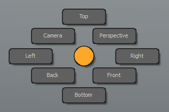
| Ctrl + Space | Pie menu with viewport options; Top, Perspective, Front Right, Bottom, Back, Right, Camera. : See Foundry.com : Pie Menu. |
| Ctrl +1 | Pie menu with many useful toggle settings, most useful ones: Toggle wire frame, Toggle Grid Workplane, Toggle Background Shading (if the non active meshes appear black). : See Foundry.com : Pie Menu. |
| Ctrl + 2 | Pie menu. Viewport shading. Show maps, wire frame, materials etc. |
| Ctrl + number | Different pie menus, test and use what you like |
| F1 | Help! Hit F1 and click on a button/feature and you will be directed to an Online Help-page containing info on the feature in question. |
| F2 | Modelling tools palette |
| F3 | Sculpting tools palette |
| F4 | Animation tools palette |
| F5 | Command history |
| F6 | Presets Viewport |
| F7 | Graph Editor |
| F8 | Render preview window |
| F10 | Render the area where the mouse cursor is |
| F11 | Snapping popover window |
| TAB | Shows the smoothed version of the mesh (same as "Turbosmooth" modifier in Max), the smoothing doesn't work outside Modo so don't use for game models |
| TAB and then -/+ | Increase and decrease the subdivision level. |
Useful Links
Sources
Video 01 : pixelfondue. [accessed June 7, 2018] MODO - Introduction to Macros. Available at: https://youtube.com/watch?v=39FJcHYzFSo
Video 02 : pixelfondue. [accessed June 7, 2018] MODO - Viewport Navigation Shortcuts. Available at: https://youtube.com/watch?v=SDvv34owpV0
Video 03 : pixelfondue. [accessed June 7, 2018] MODO - 3D Viewport Controls. Available at: https://youtube.com/watch?v=22-PPWWcWzU
Video 04 : pixelfondue. [accessed June 7, 2018] MODO - Viewport Independence. Available at: https://youtube.com/watch?v=q7HrWSpDc58
Video 05 : pixelfondue. [accessed June 7, 2018] MODO - Six Selection Tips in 60 Seconds vol.1. Available at: https://youtube.com/watch?v=uBO1k_2heOo
Video 06 : pixelfondue. [accessed June 7, 2018] MODO - Topology Symmetry. Available at: https://youtube.com/watch?v=fBZsL92B0S8
Video 07 : pixelfondue. [accessed June 7, 2018] MODO - Fix Symmetry. Available at: https://youtube.com/watch?v=XBREUbQbO3o
Video 08 : pixelfondue. [accessed June 7, 2018] MODO - Creating Instances. Available at: https://youtube.com/watch?v=RdGfeM7D5qI
Video 09 : pixelfondue. [accessed June 7, 2018] MODO - Selection Sets. Available at: https://www.youtube.com/watch?v=adsXV9HDRow
Video 10 : pixelfondue. [accessed June 7, 2018] MODO - Creating Unit Primitives. Available at: https://youtube.com/watch?v=y3Nz128Y4ZA
Video 11 : pixelfondue. [accessed June 7, 2018] MODO - Interactively Add Sides and Segments to Primitives. Available at: https://youtube.com/watch?v=ZcYsj9H2FZ0
Video 12 : pixelfondue. [accessed June 7, 2018] MODO - Thicken Tool. Available at: https://youtube.com/watch?v=JD0imTdKPsw
Video 13 : pixelfondue. [accessed June 7, 2018] MODO - Merge Vertices and Vertex Merge Tool. Available at: https://youtube.com/watch?v=SkOuJZeiuCk
Video 14 : pixelfondue. [accessed June 7, 2018] MODO - Spin Quads. Available at: https://youtube.com/watch?v=gGoJ8qoOLEA
Video 15 : pixelfondue. [accessed June 7, 2018] MODO - Polygon Split. Available at: https://youtube.com/watch?v=QQWd0XcomCs
Video 16 : pixelfondue. [accessed June 7, 2018] MODO - Bend Tool. Available at: https://youtube.com/watch?v=7bvdgV4U6F4
Video 17 : pixelfondue. [accessed June 7, 2018] MODO - Topology Pen Tool Shortcuts. Available at: https://www.youtube.com/watch?v=JIFuxhdD7dg
Video 18 : pixelfondue. [accessed June 7, 2018] MODO - Polygon Reduction Tool. Available at: https://youtube.com/watch?v=7C1PPnhobJY
Video 19 : pixelfondue. [accessed June 7, 2018] MODO - Mesh Cleanup. Available at: https://youtube.com/watch?v=5BJ0Mjyj3aA
Video 20 : pixelfondue. [accessed June 7, 2018] MODO - Dimensions Tool. Available at: https://youtube.com/watch?v=S80ICSRp7Tw
Video 21 : pixelfondue. [accessed June 7, 2018] MODO - UV Pins. Available at: https://youtube.com/watch?v=64F9kvf-B7M
Video 22 : pixelfondue. [accessed June 7, 2018] MODO - UV Alignment Tools. Available at: https://youtube.com/watch?v=X1riOHPquVE
Video 23 : pixelfondue. [accessed June 7, 2018] MODO - UV Pixel Snapping. Available at: https://youtube.com/watch?v=cxIGG-Uchtc
Video 24 : pixelfondue. [accessed June 7, 2018] MODO - UV Viewport: Backdrop Image Options. Available at: https://youtube.com/watch?v=5ikhODjp7aU
Video 25 : pixelfondue. [accessed June 7, 2018] MODO - UV Viewport: Extents. Available at: https://youtube.com/watch?v=q8Gil35WGug
Video 26 : pixelfondue. [accessed June 7, 2018] MODO - UV Viewport: Spans. Available at: https://youtube.com/watch?v=cL4MkSLklvE